A Technical Guide to Logic Locking for Chip Security
Strengthening integrated circuits against untrusted manufacturing and Trojan insertion.
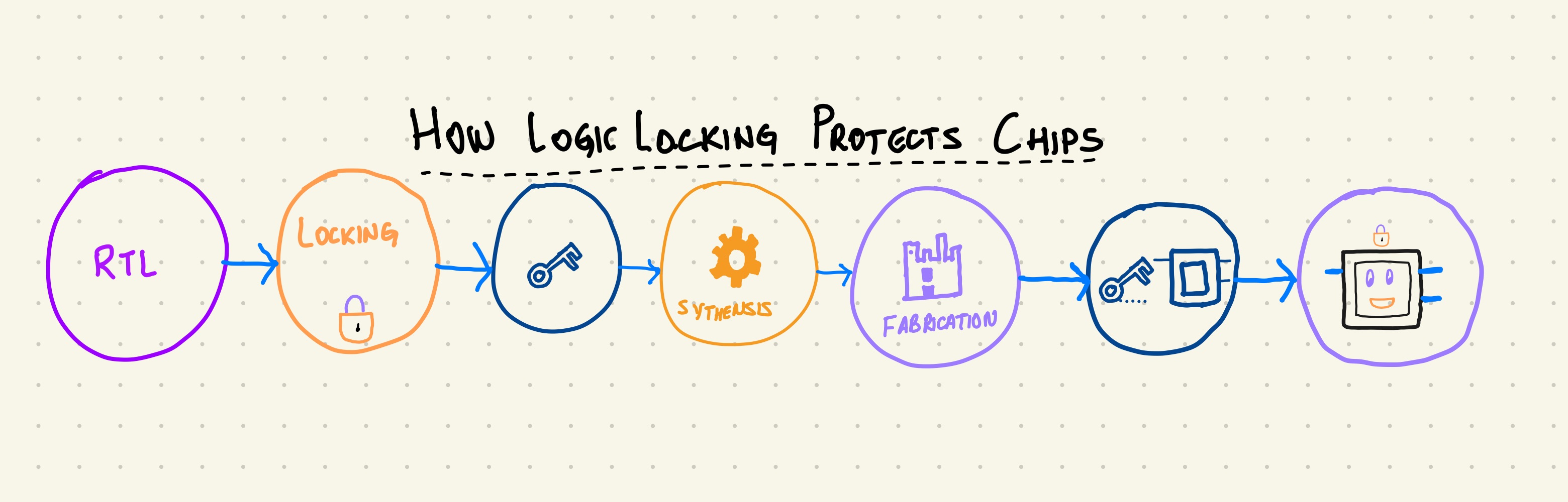
1. Introduction
As semiconductor manufacturing becomes more global, securing the design and fabrication flow has become an important concern. Most design companies use the fabless model, which means fabrication happens in external foundries. This introduces two risks:
- Unauthorized overproduction or IP theft
- Hardware Trojan insertion during mask preparation or ECO steps
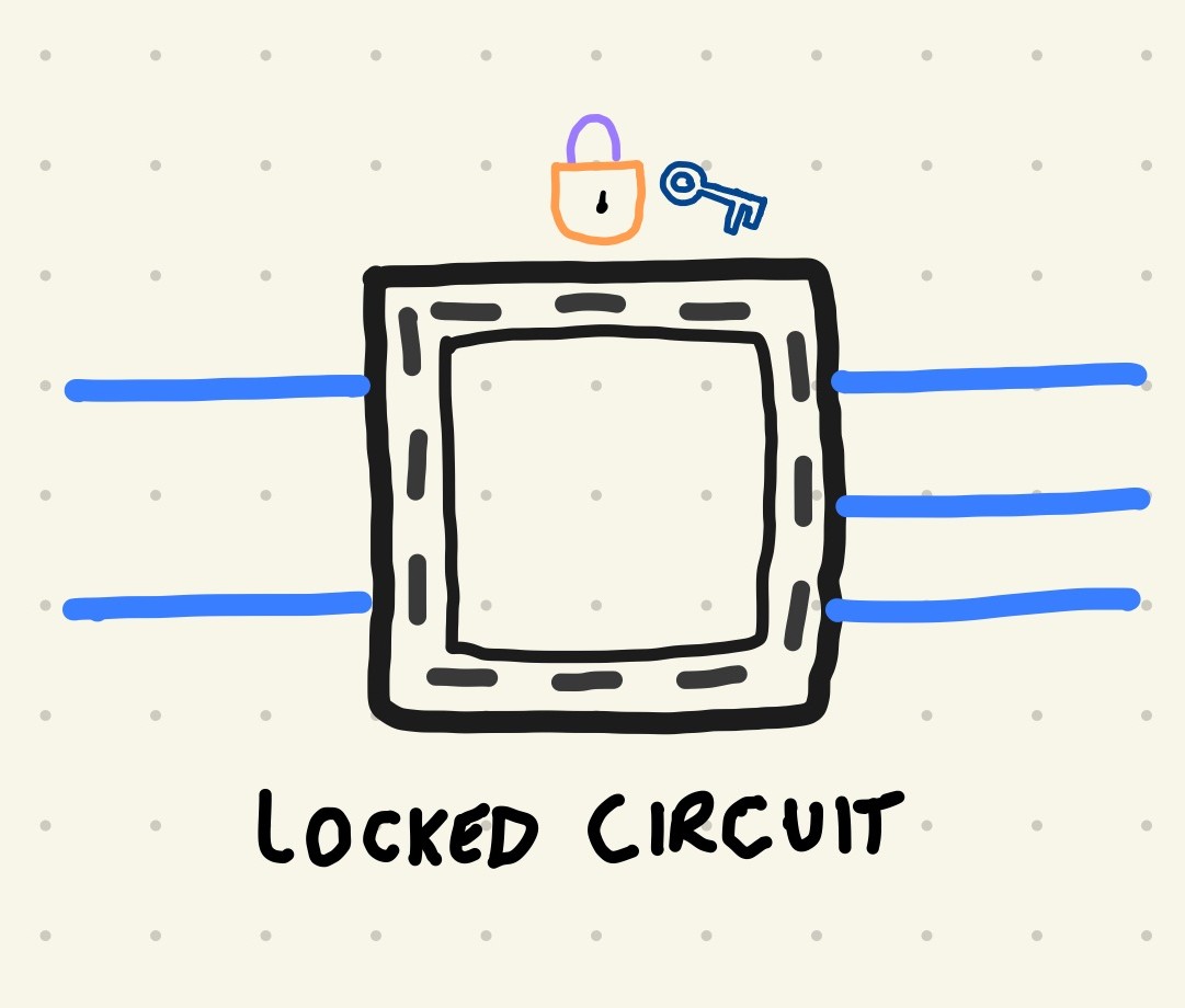
Logic locking introduces key controlled gates into an ASIC so the chip works correctly only when the correct key is applied. It protects IP and increases the difficulty of malicious modification.
2. What is Logic Locking
Logic locking adds extra gates into a circuit that depend on a secret key. Without the key, the circuit produces incorrect outputs.
Common key gate types
- XOR or XNOR gates
- MUX based key gates
- Anti SAT blocks
- SFLL (Stripped Functionality Logic Locking)
3. Simple XOR Based Locking Example
Original RTL:
assign Y = A ^ B;
If Key[0] is zero, the circuit behaves normally. If Key[0] is one, the output is flipped and downstream behavior is corrupted.
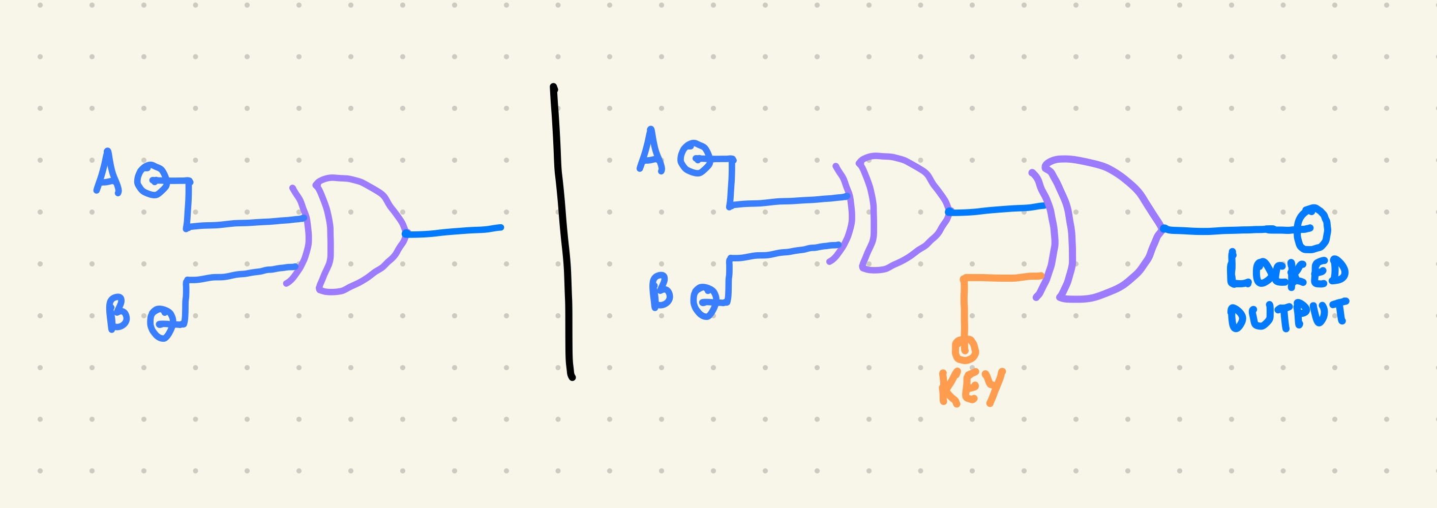
Even this small modification breaks straightforward cloning and reverse engineering.
4. Structural Impact of Locking
Adding locking logic affects several structural properties of the netlist:
- fan out of selected signals
- depth of some logic cones
- switching patterns on internal nodes
- placement of new gates in critical or non critical paths
These structural changes:
- make reverse engineering harder
- change where an attacker might try to insert a Trojan
- can be used as additional signals in detection
5. How Locking Helps Detect Hardware Trojans
Hardware Trojans often rely on:
- rare internal trigger conditions
- very low switching activity when inactive
- payloads that blend into existing logic
- predictable and stable structure
- Logic locking disrupts these assumptions.
Locking can:
- increase switching entropy around key controlled regions
- make power signatures less predictable for attackers
- force Trojans to interact with key logic to remain effective
- expose malicious structures when the wrong key is applied
When combined with switching activity localization or power analysis, this improves Trojan detectability.
6. Power Analysis Overview
Power based detection uses the fact that Trojans cause small but measurable changes in switching activity.
A simplified power model:
P_total = P_static + P_dynamic P_dynamic ∝ C_load * V^2 * f * switching_activity
Locked circuits already modify switching activity. When a Trojan activates, the deviation from the locked baseline can stand out more clearly.
Typical analysis flow:
- Run simulation on a golden (Trojan free) design
- Run simulation on a design under test
- Generate VCD or SAIF files with switching activity
- Convert toggles into power traces using synthesis or gate level tools
- Compare traces across test vectors
- Localize suspicious regions or time windows
7. MUX Based Lock Example
To avoid simple attacks that target XOR structures, many schemes use MUX based locking.
Example:
assign Y = Key[i] ? real_signal : dummy_signal;
- Correct key selects real_signal and the design behaves correctly.
- Incorrect key selects dummy_signal and the behavior is corrupted.
Properties of MUX based locking:
- harder for SAT solvers to simplify in some cases
- creates more structural ambiguity
- can be aligned with existing multiplexed datapaths
8. SAT Attack Notes
SAT attacks try to recover the secret key by generating discriminating input patterns that eliminate incorrect keys.
Basic idea:
- Treat the locked circuit as a black box with key inputs.
- Use a SAT solver to search for input patterns that behave differently under different keys.
- Iteratively narrow down the key space until the correct key is found
- Ways to strengthen locking against SAT attacks
- deeper and more distributed locking
- Anti SAT and SARLock style blocks
- SFLL mechanisms with rare corruptibility
- structural transformations after locking
- removal of obvious XOR key patterns
- mixing multiple locking styles
The goal is to make the search space and solver effort impractical.
9. RTL Example of a Locked Module
Below is a small example that shows how key bits can corrupt internal nodes.
module locked_and4(
    input  wire [3:0] A,
    input  wire [3:0] Key,
    output wire Y
);
    wire temp0, temp1;

    assign temp0 = A[0] & A[1];
    assign temp1 = A[2] & A[3];

    // Insert XOR based key gates
    assign Y = (temp0 ^ Key[0]) & (temp1 ^ Key[1]);
endmodule
This design:
- behaves correctly only when Key[0] and Key[1] match the intended values
- corrupts the output for incorrect keys
- introduces new logic cones and switching patterns
10. Engineering Guidelines for Logic Locking
Some practical guidelines when applying locking in real flows:
- distribute key gates across different blocks instead of clustering them
- avoid adding locks only at outputs, which is easier to attack
- combine logic locking with scan chain obfuscation and secure test
- use synthesis remapping to hide simple locking patterns
- avoid locking the most timing critical paths
- evaluate area, power, and timing overhead for each scheme
- test golden versus locked designs with realistic workloads

11. Tools and Frameworks
Common tools used for logic locking and evaluation include:
- Yosys for open source synthesis and simple flows
- Commercial tools like Synopsys Design Compiler and Cadence Genus
- TrustHub benchmarks for hardware Trojan evaluation
- SAT attack frameworks for key recovery experiments
- PrimeTime PX or similar tools for power estimation
- Python scripts for VCD parsing and trace analysis
These can be combined into reproducible experiments in a public GitHub repository.
12. Conclusion
Logic locking is a practical and flexible method for protecting integrated circuits built in untrusted environments. It raises the difficulty of cloning and reverse engineering and can improve hardware Trojan detection when combined with structural and power based analysis.
As semiconductor supply chains remain globally distributed, design for trust techniques like logic locking will continue to be an important part of secure hardware design.
This page is part of a larger set of hardware security and ASIC design notes.